- 您现在的位置:买卖IC网 > Sheet目录1991 > CS4398-CZZ (Cirrus Logic Inc)IC DAC 120DB 192KHZ W/VC 28TSSOP
DS568F1
17
CS4398
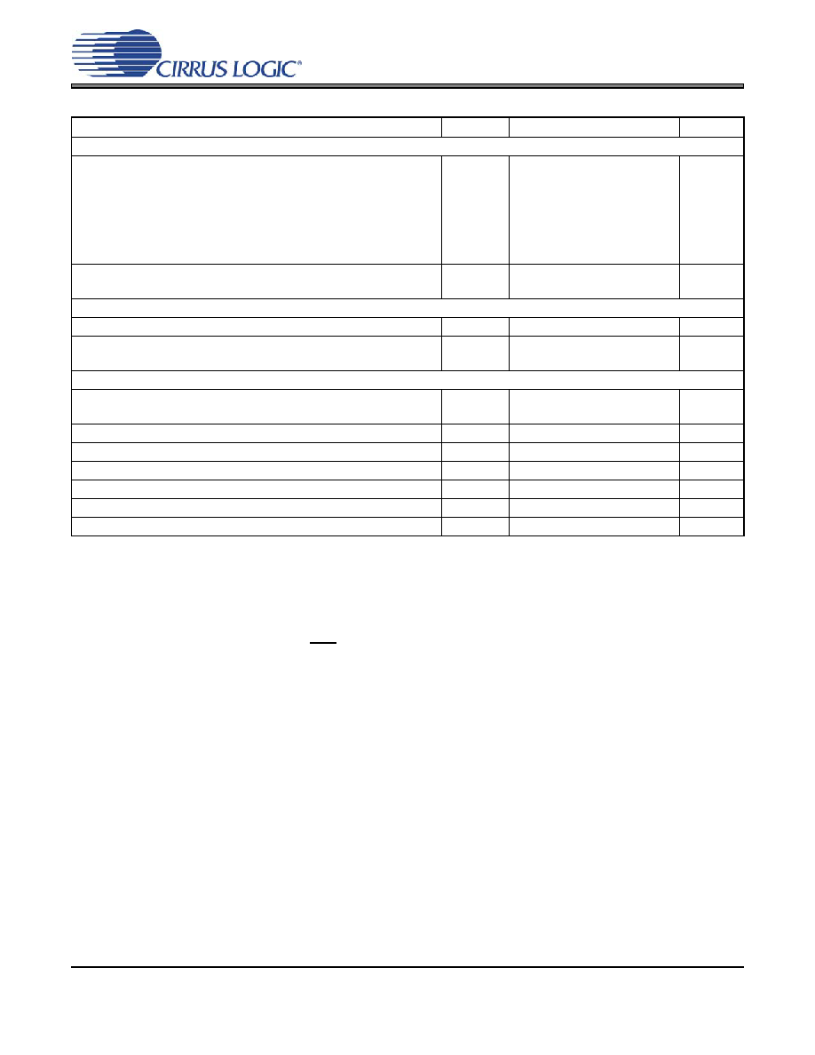
DC ELECTRICAL CHARACTERISTICS
16. Normal operation is defined as RST pin = High with a 997 Hz, 0 dBFS input sampled at the highest Fs for
each speed mode, and open outputs, unless otherwise specified.
17. IA measured with no loading on the AMUTEC and BMUTEC pins.
18. ILC measured with no external loading on pin 11 (SDA).
19. Power-Down mode is defined as RST pin = Low with all clock and data lines held static.
20. Valid with the recommended capacitor values on FILT+ and VQ as shown in the “Typical Connection Dia-
21. This current is sourced/sinked directly from the VA supply.
Parameters
Symbol
Min
Typ
Max
Units
Normal Operation (Note 16)
Power Supply Current
Vref= 5 V
VD = 5 V
VD = 3.3 V
Interface current (Note 18)
IA
Iref
ID
ILC
ILS
-
25
1.5
25
18
2
80
28
2
38
27
-
mA
A
Power Dissipation
VA = 5 V, VD = 5 V
VA = 5 V, VD = 3.3 V
-
258
192
340
240
mW
Power-Down Mode (Note 19)
Power Supply Current
Ipd
-200
-
A
Power Dissipation
VA = 5 V, VD = 5 V
VA = 5 V, VD = 3.3 V
-
1
-
mW
All Modes of Operation
Power Supply Rejection Ratio (Note 20)
(1 kHz)
(60 Hz)
PSRR
-
60
40
-
dB
Common Mode Voltage
VQ
-
0.5VA
-V
Max Current draw from VQ
IQmax
-1-
A
FILT+ Nominal Voltage
-
0.93VA
-V
Maximum MUTEC Drive Current
(Note 21)
-
3
-
mA
MUTEC High-Level Output Voltage
VOH
VA
V
MUTEC Low-Level Output Voltage
VOL
0V
发布紧急采购,3分钟左右您将得到回复。
相关PDF资料
CS43L22-CNZR
IC DAC W/HDPN & SPKR AMPS 40-QFN
CS4461-CZZR
IC ADC PSR FEEDBACK 24-TSSOP
CS5340-CZZ
IC ADC AUD 101DB 200KHZ 16-TSSOP
CS5340-DZZR
IC ADC AUD 101DB 200KHZ 16-TSSOP
CS5341-DZZ
IC ADC AUD 105DB 200KHZ 16-TSSOP
CS5342-CZZ
IC ADC AUD 105DB 200KHZ 16-TSSOP
CS5345-CQZ
IC ADC AUD 104DB 200KHZ 48-LQFP
CS5345-DQZ
IC ADC AUD 104DB 200KHZ 48-LQFP
相关代理商/技术参数
CS4398-CZZR
功能描述:数模转换器- DAC IC 120dB 192kHz Mlt-Bt DAC w/Volctrl RoHS:否 制造商:Texas Instruments 转换器数量:1 DAC 输出端数量:1 转换速率:2 MSPs 分辨率:16 bit 接口类型:QSPI, SPI, Serial (3-Wire, Microwire) 稳定时间:1 us 最大工作温度:+ 85 C 安装风格:SMD/SMT 封装 / 箱体:SOIC-14 封装:Tube
CS4399-CNZ
功能描述:HIPRFDACINTGHPDRIVR&IMPED DETCTN 制造商:cirrus logic inc. 系列:* 包装:托盘 零件状态:在售 安装类型:表面贴装 封装/外壳:40-WFQFN 裸露焊盘 供应商器件封装:40-QFN(5x5) 标准包装:490
CS4399-CNZR
功能描述:HIPRFDACINTGHPDRIVR&IMPED DETCTN 制造商:cirrus logic inc. 系列:* 包装:剪切带(CT) 零件状态:在售 安装类型:表面贴装 封装/外壳:40-WFQFN 裸露焊盘 供应商器件封装:40-QFN(5x5) 标准包装:1
CS4399-CWZR
功能描述:HIPRFDACINTGHPDRIVR&IMPED DETCTN 制造商:cirrus logic inc. 系列:* 包装:剪切带(CT) 零件状态:在售 安装类型:表面贴装 封装/外壳:42-UFBGA,WLCSP 供应商器件封装:42-WLCSP 标准包装:1
CS43L21
制造商:CIRRUS 制造商全称:Cirrus Logic 功能描述:Low Power, Stereo Digital to Analog Converter
CS43L21-CNZ
功能描述:音频数/模转换器 IC Low Power Stereo DAC 24-Bits 96kHz 98dB RoHS:否 制造商:Texas Instruments 转换器数量: 分辨率:16 bit 接口类型:I2S, UBS 转换速率: 信噪比:98 dB 工作电源电压:5 V DAC 输出端数量:2 工作温度范围:- 25 C to + 85 C 电源电流:23 mA 安装风格:SMD/SMT 封装 / 箱体:TQFP-32 封装:Reel
CS43L21-CNZR
功能描述:数模转换器- DAC IC 98dB 96kHz Low PWR Stereo DAC RoHS:否 制造商:Texas Instruments 转换器数量:1 DAC 输出端数量:1 转换速率:2 MSPs 分辨率:16 bit 接口类型:QSPI, SPI, Serial (3-Wire, Microwire) 稳定时间:1 us 最大工作温度:+ 85 C 安装风格:SMD/SMT 封装 / 箱体:SOIC-14 封装:Tube
CS43L21-DNZ
功能描述:数模转换器- DAC CS43L21-DNZ MS Audio Portable part. RoHS:否 制造商:Texas Instruments 转换器数量:1 DAC 输出端数量:1 转换速率:2 MSPs 分辨率:16 bit 接口类型:QSPI, SPI, Serial (3-Wire, Microwire) 稳定时间:1 us 最大工作温度:+ 85 C 安装风格:SMD/SMT 封装 / 箱体:SOIC-14 封装:Tube